Tropfenfotografie mit Raspberry und Lichtschranke
In der c’t Hardware Hacks 01/13 wurde beschrieben, wie man Tropfen fotografiert. Der Aufbau basierte auf einem Arduino.
Dieser Artikel beschreibt die Umsetzung mit einem Raspberry Pi.
Weiterhin habe ich Funkauslöser für Kamera und Blitz eingesetzt.
(Eine Zeitmessung mit zwei Lichtschranken findet man hier: https://hoeser-medien.de/?p=1212)
Für Einstellungen der Kamera gibt es hier Ratschläge: http://www.tropfenfotografie.de/

Weitere Bilder gibt es hier: klick
Aufbau
Beim ersten Versuch habe ich eine Spritze genommen. Später soll an dem Galgen eine Flasche hängen.
Die Schraube dient dazu, die Kamera zu fokussieren.
Hinter der mattierten Scheibe befindet sich ein zweiter Blitz.
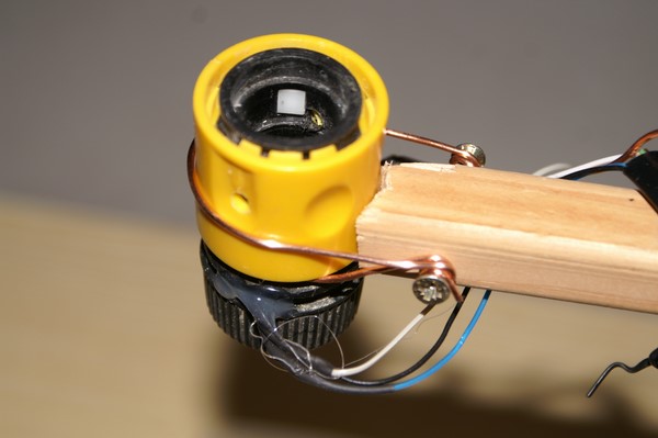
Die Gartenschlauch-Kupplung dient als Lichtschranke. Unten wurde ein entsprechendes Loch gebohrt, um die IR-Diode bzw. den Fototransistor einzuführen.
Was wird benötigt ?
- Digitalkamera
Funkauslöser (optional)Funktioniert nicht: Siehe Validation ganz unten- Studioblitz (optional)
- Raspberrry PI
- Elektronik-Interface (s.u.)
- Software:
- flash.c (s.u.)
- wiringPI
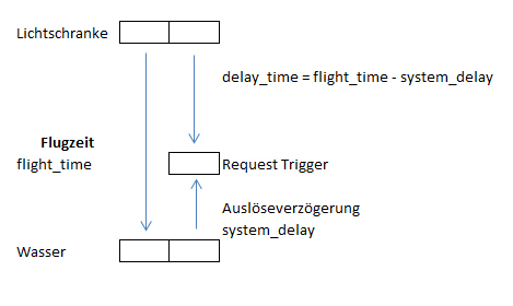
Systemberechnung
Hardware Lichtschranke
Die Lichtschranke besteht aus einer IR-LED CQY37N und einem Fototransistor BPW17N.
Gekauft bei ebay „NPN PHOTOTRANSISTO
Die Schaltung basiert auf der Anleitung bei http://www.strippenstrolch.de/1-2-12-der-reflexkoppler-cny70.html Der Fototransistor steuert ein Schmitt-Trigger, um ein sauberes Ausgangssignal zu erhalten.
Funkauslöser
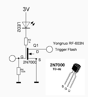
Ein Funkauslöser ist nicht notwendig, erlaubt jedoch eine flexibel Aufbau. Den Funkauslöser von Yongnuo setze ich für Portraitfotos bereits ein. Hier kann man dies sehen: klick.
Die Schaltung ist relativ und basiert auf einem 2N7000.
Man kann die Treiberstufe mit einem Transistor oder Mos-FET realisieren. Ich hatte den 2N7000 verfügbar und habe daher diesen verwendet.
Software
Die Auslösung der Lichtschranke wird über einen Interrupt erkannt. WiringPi bietet eine einfache Lösung hierfür. In der Interrupt-Service-Routine (ISR) wird eine bestimmte Zeit gewartet, und dann der Ausgang geschaltet. Nach jedem Interrupt, wird die Wartezeit etwas erhöht, um den Tropfen in verschiedenen Phasen zu fotografieren.
Installation wiringPi
[codesyntax lang="text"]
cd
git clone git://git.drogon.net/wiringPi
cd wiringPi
./build
[/codesyntax]
Installation argtable2
[codesyntax lang="text"]
sudo apt-get install libargtable2-dev
cd git clone git://git.drogon.net/wiringPi cd wiringPi ./build
[/codesyntax]

Makefile und Program liegen auf GitHUB:
[codesyntax lang=“text“]
cd; mkdir -p git; cd git
git clone git://github.com/ThomasH-W/Tropfenfotografie
[/codesyntax]
Makefile
[codesyntax lang=“text“]
# -----------------------------------------
# makefile V0.2 2014-01-12 Thomas Hoeser
# do not use space at the beginning of a line – use tab only !
# -----------------------------------------

CC=gcc
# CFLAGS =I. -I/usr/local/include -Wall -ansi -O0
CFLAGS=-I. -lwiringPi -largtable2

LDFLAGS = -L/usr/lib
LDLIBS = -largtable2

PROJ=flash
RELEASEDIR=.
RASP-IP=192.168.178.61

all: prepare $(PROJ)
    @echo "------------------------ Fertig"

debug: prepare flash_ debug

# w/o : no echo of the command
prepare:
    @echo "Ich fang jetzt an!"

# w/o error message : - at the beginning
clean:
    -rm -f $(PROJ) $(PROJ).o

release:
    @echo “copy file $(PROJ) via ftp to raspberry $(RASP-IP)”

$(PROJ): $(PROJ).c
    $(CC) $(CFLAGS) -o $(PROJ) $(PROJ).c

flash_debug: flash.c
    gcc gcc –DMYDEBUG flash.c …..

help:
    @echo
    @echo "Aufruf   : make target"
    @echo
    @echo "Targets  : help    - Zeigt diesen Text an."
    @echo "           all     - Erstellt das Ziel $(PROJ)"
    @echo "           release - Kopiert $(PROJ) nach $(RELEASEDIR)"
    @echo "           clean   - Löscht die Ergebnisdateien (*.o, usw.)."
    @echo
    @echo "Beispiele: make all"
    @echo "           make clean"
    @echo
[/codesyntax]
Flash.c
[codesyntax lang=“text“]
/*
 * flash.c:
 *    This progam is used to trigger a digital camera utilizing a light barrier
 *
 * git clone git://git.drogon.net/wiringPi
 * cd wiringPi
 * ./build
 *
 * sudo apt-get install libargtable2-dev
 *
 * gcc -lwiringPi -o flash flash.c
 *
 */
#include <stdio.h>
#include <string.h>
#include <stdlib.h>
#include <sys/time.h>
#include <wiringPi.h>
#include <argtable2.h>  // argopt
#include <errno.h>

#define PROGNAME         flash
#define MYDEBUG_NO

// Which GPIO pin we're using
#define PIN_IN         3    // GPIO 22 - header PIN 15
#define PIN_RELAYS     4    // GPIO 23 - header PIN 16
#define PIN_LED     5    // GPIO 24 - header PIN 18

/* --------------------------------------------------------
 * There are 8 available GPIO Pins on Raspberry Pi
 *                         wirPi        PIN  |  PIN   wirPi
 *                     ------------------|---------------
 * 3.3V,Vdd,Vcc              1         2     |                    5V
 * SDA                           8         3     |     4                5V
 * SCL                          9         5     |     6                  GND, Vss, Vee
 * 1-Wire    GPIO  4         7         7     |     8        15        UART TXD
 *                                        9     |    10        16         UART RXD
 *             GPIO 17          0         11  |    12         1        GPIO 18    PCM CLK
 *             GPIO 21            2         13     |    14                GND, Vss, Vee
 *             GPIO 22           3         15  |    16         4        GPIO 23
 * 3.3V,Vdd,Vcc                      17  |    18         5        GPIO 24
 * MOSI                     12         19  |    20                 GND, Vss, Vee
 * MISO                           13         20  |    22         6        GPIO 25
 * SCLK                         14         23     |    24        10        CE0
 * GND, Vss, Vee                        25     |    26        11        CE1
 */

struct timeval last_change       ;  // Time of last change

static volatile int globalDropCnt = 0 ;    // Count drops recognized
static volatile int t_wait_start  = 0 ;    // Count drops recognized
static volatile int t_wait_incr   = 0 ;    // Count drops recognized
static volatile int t_sysdelay    = 0 ;    // Count drops recognized

// How much time a change must be since the last in order to count as a change
#define IGNORE_CHANGE_BELOW_USEC 2000000 // 1 s
// s =    4,91 [m/s]    *    t2 [s]
// t 2 =    s    /    4,91 [m/s]
#define FLIGHT_MSEC         140 // 140ms    // time between input signal and trigger output
#define SYSDELAY_MSEC        20 //  20ms    // system (camara, remote) delay
#define FLIGHT_INCR_MSEC   40    //  40ms    // offset to FLIGHT_MSEC
#define FLASH_MSEC          320 // 320ms    // lenght of output signal for camera

// 1 Sekunde = 1000 Millisekunden = 1000000 Mikrosekunden = 10-6 Mikrosekunden
// 1 Millisekunden = 1000 Mikrosekunden
// 1 Mikrosekunde (µs) = 1000 Nanosekunden = 0,000 001 Sekunden = 10-6 Sekunden

// -------------------------------------------------------------------------------------
// toggle state for given time
void output_blink(int OUTPUT_PIN, int BLINK_TIME) {

    static volatile int state;       // define variable for state of the pin
    state = digitalRead(OUTPUT_PIN); // Get current state of pin

    digitalWrite (OUTPUT_PIN, !state) ;    // set pin to inverse state
    delay (BLINK_TIME) ;                // wait for given time [milliseconds]
    digitalWrite (OUTPUT_PIN, state) ;    // set pin to original state
}
// -------------------------------------------------------------------------------------
void myStandardFunc(void)
{ printf ("STD  - Global Counter = %d\n",++t_wait_start); } // end myStandardFunc()
// -------------------------------------------------------------------------------------
// Handler for interrupt
void myInterrupt(void) {
    static struct timeval t_begin,t_end;
    static unsigned long diff;
    static int t_delay,seconds,useconds;

    gettimeofday(&t_begin, NULL); // get current time and save in variable t_begin

    // Time difference in usec
    diff = (t_begin.tv_sec * 1000000 + t_begin.tv_usec) - (last_change.tv_sec * 1000000 + last_change.tv_usec);

    if (diff > IGNORE_CHANGE_BELOW_USEC) {  // Filter jitter
    t_delay = (t_wait_start + globalDropCnt* t_wait_incr - t_sysdelay );

    #ifdef MYDEBUG
    printf("flight start    :  %d \n",t_wait_start);
    printf("system delay    : -%d \n",t_sysdelay);
    printf("flight increment:  %d \n",t_wait_incr );
    printf("net delay       :  %d \n",t_delay );
    #endif

      globalDropCnt ++;
    delay(t_delay) ;                         // wait for flight from light barrier to water surface

    gettimeofday(&t_end, NULL);            // get current time and save in variable t_end
      output_blink(PIN_RELAYS, FLASH_MSEC ); // Trigger Flash

      seconds  = t_end.tv_sec  - t_begin.tv_sec;
      useconds = t_end.tv_usec - t_begin.tv_usec;
      if(useconds < 0) {
        useconds += 1000000;
        seconds--;
        }
      printf("Interrupt #%d -> delay: %d -> var start/end: %d sec %d msec\n\n",globalDropCnt, t_delay, seconds, useconds/1000);
    // flight_start =   useconds; // dummy code
      output_blink(PIN_LED, 200 );

    } // if - Filter jitter

    last_change = t_begin;
} // myInterrupt()

// -------------------------------------------------------------------------------------
int mymain(int flight_start, int flight_incr, int sysdelay)
  {
  t_wait_start = flight_start;
  t_wait_incr  = flight_incr;
  t_sysdelay   = sysdelay;

  printf("flight_start   : %d \n",t_wait_start);
  printf("sysdelay       : %d \n",t_sysdelay);
  printf("flight_incr    : %d \n",t_wait_incr );

    globalDropCnt=0;                     // init counters
    gettimeofday(&last_change, NULL);     // Time now

    wiringPiSetup();                    // Init
    pinMode (PIN_RELAYS, OUTPUT) ;  // Set pin to output in case it's not
    pinMode (PIN_LED,    OUTPUT) ;  // Set pin to output in case it's not
    digitalWrite (PIN_LED,HIGH);        // Set pin to low
    wiringPiISR(PIN_IN, INT_EDGE_RISING, &myInterrupt);  // Bind to interrupt

  printf("flash - wait for drop ....\n\n");
  output_blink(PIN_LED, 500);
    // Waste time but not CPU
    for (;;) {
        sleep(1000);
    } // for

  return 0;
} // mymain()
// -------------------------------------------------------------------------------------
// http://argtable.sourceforge.net/example/myprog.c
//
int main(int argc, char **argv) {

    struct arg_int* aflight_start = arg_int0("s","start",NULL,       "start     (default is 100)");
    struct arg_int* aflight_incr  = arg_int0("i","increment",NULL,   "increment (default is 10)");
    struct arg_int* asysdelay     = arg_int0("d","delay",NULL,       "delay     (default is 20)");
    struct arg_lit* help         = arg_lit0(NULL,"help",            "print this help and exit");
    struct arg_lit* version      = arg_lit0(NULL,"version",         "print version information and exit");
    struct arg_end* end          = arg_end(20);
    void* argtable[] = {aflight_start,aflight_incr,asysdelay,help,version,end};
    const char* progname = "flash";
    int nerrors;
    int exitcode=0;

    /* verify the argtable[] entries were allocated sucessfully */
    if (arg_nullcheck(argtable) != 0)
        {
        /* NULL entries were detected, some allocations must have failed */
        printf("%s: insufficient memory\n",progname);
        exitcode=1;
        goto exit;
        }

    /* set any command line default values prior to parsing */
    aflight_start->ival[0] = FLIGHT_MSEC;
    aflight_incr ->ival[0] = FLIGHT_INCR_MSEC;
    asysdelay    ->ival[0] = SYSDELAY_MSEC;

    /* Parse the command line as defined by argtable[] */
    nerrors = arg_parse(argc,argv,argtable);

    /* special case: '--help' takes precedence over error reporting */
    if (help->count > 0)
        {
        printf("Usage: %s", progname);
        arg_print_syntax(stdout,argtable,"\n");
        printf("This program demonstrates the use of the argtable2 library\n");
        arg_print_glossary(stdout,argtable,"  %-25s %s\n");
        exitcode=0;
        goto exit;
        }

    /* special case: '--version' takes precedence error reporting */
    if (version->count > 0)
        {
        printf("'%s' trigger camera based on light gate\n",progname);
        printf("January 2014, Thomas Hoeser\n");
        exitcode=0;
        goto exit;
        }

    /* If the parser returned any errors then display them and exit */
    if (nerrors > 0)
        {
        /* Display the error details contained in the arg_end struct.*/
        arg_print_errors(stdout,end,progname);
        printf("Try '%s --help' for more information.\n",progname);
        exitcode=1;
        goto exit;
        }

/* normal case: take the command line options at face value */
exitcode = mymain(aflight_start->ival[0],aflight_incr->ival[0], asysdelay->ival[0]);

exit:
    /* deallocate each non-null entry in argtable[] */
    arg_freetable(argtable,sizeof(argtable)/sizeof(argtable[0]));

    return exitcode;
} // main()
[/codesyntax]
Programm compilieren + starten
[codesyntax lang=“text“]
make
sudo ./flash
[/codesyntax]
Anpassung für den Testaufbau:
[codesyntax lang=“text“]
sudo ./flash -s 100 -i 10 -d 20
[/codesyntax]
Parameter
- -s 100 # Fallzeit erechnet auf Fallhöhe
- -i 10 # Inkrement für den nächsten Durchlauf
- -d 20 # Auslöseverzögerung (Funkauslöser + Kamera)
Validation der Schaltung / Software
Am Anfang hat sich der Aufbau nicht wie erwartet verhalten. Mit einem LogicAnalyzer habe ich dies dann nachgeprüft. Die Verzögerung des Funkauslösers war größer, als ich erwartet hatte.
Lichtschranke -> GPIO-Funksender: 80,2 ms ; Also fast genau der Zeitvorgabe des Raspberry.
GPIO-Funksender -> Kamera -> Empfänger Studioblitz: 0,41 s = 410 ms d.h. eine Verzögerung durch die Kamera von 410ms -> dies entsprichet einer Fallhöhe 82 cm
2. Versuch GPIO-Funksender -> Kamera -> Empfänger Studioblitz: 0,317 s = 317 ms
Noch schlimmer: Die Verzögerung durch die Kamera ist nicht konstant!
Ergo: die Aufnahmen mit Funkauslösung sind nicht zuverlässig. Die Kamera muss mit einem Kabel verbunden werden.


