
LED Suit with Arduino and RF Receiver NRF24L01 (Tron style)

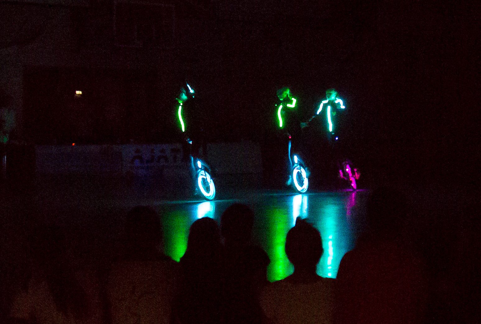
Das folgende System soll die Lichteffekte der Darsteller über einen PC steuern.
Somit kann man auf dem PC/Notebook flexibel die Show entwickeln.
Zum Einsatz kommt das kostenlose Program Vixen.
Die Technik basiert auf dem DMX512 Protokoll, damit man offen für bestehende Anlagen ist.
Weiterhin läßt sich dann das System mit handlsüblichen Leuchten erweitern.
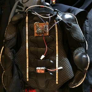
Die Hardware besteht aus arduino mit den Funkmodulen NRF24L01.
Für den ersten Test, wurde die RGB-Streifen auf eine Schutzweste genäht.
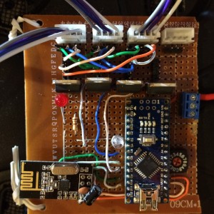
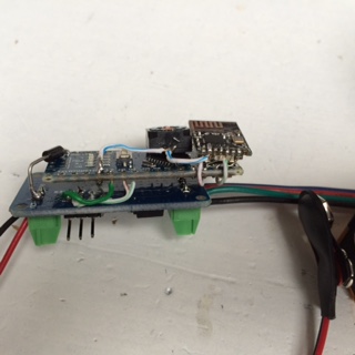
2. Version mit Arduino Nano, nRF24L01 SMD und LED Driver P9813


Receiver Code
[codesyntax lang=”c”]
/*
 * RFShowControl Receiver code
 *
 *    In    : nRF
 *    Out   : P9813 + RGB
 *    Date	: 2016-05-02
 *    WORKS WITH PAR56 INTIAL SETUP
 *
 * Created on: Mar 2013 * Updated 6/2/2013
 * Author: Greg Scull, komby@komby.com * Updated: May 18, 2014 - Mat Mrosko, Materdaddy, rfpixelcontrol@matmrosko.com
 *
 * ToDo - define module type  Pxxx, 4PWM
 *
 * Hardware Setup
 * decoder on analog inputs
 *     A0..A3 -> select Pixel-Set, a group of DMX channels
 *     A4+A5  -> offset within Pixel-Set
 *     A6+A7  -> select RF channel
 * nRF24 on CE9 CS10 - defined via include
 * P9813 decoder on 2+3
 *
*/
#include <Arduino.h>

#include <EEPROM.h>
#include <nRF24L01.h>
#include <RF24.h>
#include <SPI.h>
#include <printf.h>

#include "IRFShowControl.h"
#include "RFShowControl.h"

#include <ChainableLED.h>

#define DEBUG_
#define TIME_ALIVE		1000
#define TIME_POWEROFF	3000
/********************* START OF REQUIRED CONFIGURATION ***********************/
#define RECEIVER_UNIQUE_ID              41 // Valid Values: 1-255
uint8_t dec_RFChannel[] = {0, 10, 20,40};
#define DATA_RATE                       RF24_1MBPS  // Valid Values: RF24_250KBPS, RF24_1MBPS
#define HARDCODED_NUM_CHANNELS          12	// Valid Values: 3, 4

#define RF_LED_PIN                      4	// NO PWM
#define RED_PIN                         5	// PWM
#define GREEN_PIN                       6	// PWM
#define BLUE_PIN                        7	// NO PWM
// #define WHITE_PIN                       9 // Pin 9 reserved for nRF24
#define	P9813_CLK						2 // NO PWM
#define P9813_DATA						3 // PWM
#define NUM_LEDS    					5
#define DMX_SET     					12
// Pixel
#define DEC_PIX_1 	A5	//  1 * 2^1 = 1 * 2
#define DEC_PIX_0 	A4  //  1 * 2^0 = 1 * 1
// RF channel
#define DEC_RFC_1 	A7	//  1 * 2^1 = 1 * 2
#define DEC_RFC_0 	A6  //  1 * 2^0 = 1 * 1
// coder: 4 switches linked to ground; values 16 (0..15)
#define DEC_CH1 	A3 // Decoder Channel 1 = 1 * 2^0 = 1 * 1
#define DEC_CH2 	A2 // Decoder Channel 2 = 1 * 2^1 = 1 * 2
#define DEC_CH3 	A1 // Decoder Channel 3 = 1 * 2^2 = 1 * 4
#define DEC_CH4 	A0 // Decoder Channel 4 = 1 * 2^3 = 1 * 8

#define OVER_THE_AIR_CONFIG_ENABLE      0
#define FCC_RESTRICT 1  //Valid Values: 1, 0 // 1: disable protected channels
#define PIXEL_TYPE       NONE
//Include this after all configuration variables are set
#include "RFShowControlConfigCE9CS10.h"

//ChainableLED(byte clk_pin, byte data_pin, byte number_of_leds)
ChainableLED leds(P9813_CLK, P9813_DATA, NUM_LEDS);


// byte 	*buffer;
uint8_t *buffer;
uint8_t *bufferLED1;
uint8_t *bufferLED2;
uint8_t *bufferLED3;
uint8_t *bufferLED4;
uint8_t code_prog       = 0;
uint8_t	code_val 		= 0;
uint8_t dmxCh           = 0;
uint8_t dmxStartChannel = 0;
uint8_t dec_Pixel    [] = { 0, 3, 6,7};

uint8_t	i = 0;
unsigned long tempTimer, flashTimer, aliveTimer, powerOffTimer;

void P9813_test(void);
void dumbRGBShow(int r, int g, int b, int w, int d);
uint8_t read_coder2(uint8_t DEC_PIN_0,uint8_t DEC_PIN_1);
uint8_t read_coder4(uint8_t DEC_PIN_0,uint8_t DEC_PIN_1,uint8_t DEC_PIN_2,uint8_t DEC_PIN_3);

//---------------------------------------------------------------------------------------------------
void setup(void)
{
  uint8_t myRFChannel = 0;

#ifdef DEBUG
  Serial.begin(115200);
  printf_begin();
  printf("\n\n_______________________________________________  nRF24L01 RF In, RGB Out\n");
#endif

  pinMode(P9813_CLK , OUTPUT);
  pinMode(P9813_DATA, OUTPUT);

  pinMode(RF_LED_PIN , OUTPUT);
  pinMode(   RED_PIN , OUTPUT);
  pinMode( GREEN_PIN , OUTPUT);
  pinMode(  BLUE_PIN , OUTPUT);

  leds.init();
  leds.setColorRGB(0, 0, 0, 0);

   // setup coder input
  digitalWrite(DEC_PIX_1, HIGH);  // set pullup on analog pin 0
  digitalWrite(DEC_PIX_0, HIGH);  // set pullup on analog pin 1
  digitalWrite(DEC_RFC_1, HIGH);  // set pullup on analog pin 2
  digitalWrite(DEC_RFC_0, HIGH);  // set pullup on analog pin 3
  digitalWrite(DEC_CH1  , HIGH);  // set pullup on analog pin 0
  digitalWrite(DEC_CH2  , HIGH);  // set pullup on analog pin 1
  digitalWrite(DEC_CH3  , HIGH);  // set pullup on analog pin 2
  digitalWrite(DEC_CH4  , HIGH);  // set pullup on analog pin 3
  delay(20);

  // read coder to determine 1st DMX Channel of a set
  code_prog = read_coder4(DEC_CH1,DEC_CH2,DEC_CH3,DEC_CH4);
  if (code_prog<10) {
    dmxCh = code_prog * DMX_SET;
  }
  else {
    dmxCh = 0;
  }
  dmxStartChannel = 1 + dmxCh;

  // read analog input to determine RF Channel
  code_val = read_coder2(DEC_RFC_0,DEC_RFC_1);
  myRFChannel = dec_RFChannel[code_val];  // dec_RFChannel[] = {0, 10, 0,20};

  // NEW CODE
  radio.EnableOverTheAirConfiguration(OVER_THE_AIR_CONFIG_ENABLE);
  uint8_t logicalControllerNumber = 0;
  if(!OVER_THE_AIR_CONFIG_ENABLE)
  {
     radio.AddLogicalController(logicalControllerNumber, dmxStartChannel, HARDCODED_NUM_CHANNELS, 0);
     // radio.AddLogicalController(logicalControllerNumber, HARDCODED_START_CHANNEL, HARDCODED_NUM_CHANNELS, 0);
  }
  delay(20);
  radio.Initialize(radio.RECEIVER, pipes, myRFChannel, DATA_RATE, RECEIVER_UNIQUE_ID);
#ifdef DEBUG
  radio.printDetails();
#endif
  delay(100);
  buffer = radio.GetControllerDataBase(0);

  code_val  = read_coder2(DEC_PIX_0,DEC_PIX_1);   			// read analog input to determine Pixel
  bufferLED1 = &buffer[0+code_val];
  bufferLED2 = &buffer[1+code_val];
  bufferLED3 = &buffer[2+code_val];
  bufferLED4 = &buffer[3+code_val];
  // delay (100); //needed or leftover code?

#ifdef DEBUG
  int numChannels = radio.GetNumberOfChannels(logicalControllerNumber);
  printf("-> DMX Channel      : %2d \n",dmxCh);
  printf("-> DMX Start Channel: %2d \n",dmxStartChannel);
  printf("-> Channels         : %2d \n",numChannels);
  if (radio.isPVariant())  //Test for Plus Version
	   printf("-> RF Version       : nRF24L01+ (Plus Version)\n");
  else printf("-> RF Version       : nRF24L01 (non Plus version)\n");
  printf("-> RF Channel       : %2d \n",radio.GetChannel());
  printf("-> RF data rate     : %2d \n",DATA_RATE);
  printf("> blink ... \n");
#endif

  analogWrite(RF_LED_PIN, 200);
  leds.setColorRGB(0, 100, 0, 0);
  dumbRGBShow(255, 0, 0, 0, 400);

  analogWrite(RF_LED_PIN, 0);
  leds.setColorRGB(0, 0, 100, 0);
  dumbRGBShow(0, 255, 0, 0, 400);

  analogWrite(RF_LED_PIN, 200);
  leds.setColorRGB(0, 0, 0, 100);
  dumbRGBShow(0, 0, 255, 0, 400);

  analogWrite(RF_LED_PIN, 0);
  leds.setColorRGB(0, 0, 0, 0);
  dumbRGBShow(0, 0, 0, 0, 1);

#ifdef DEBUG
  printf("> setup() complete, loop() ... \n");
#endif
  tempTimer = flashTimer = aliveTimer = powerOffTimer = millis(); // start timing for DMX refresh on TX
} // end of setup()

//---------------------------------------------------------------------------------------------------
void loop(void)
{
if (code_prog<10) { // light show mode

  tempTimer = millis();

  if (radio.Listen()) {

	dumbRGBShow(*bufferLED1, *bufferLED2, *bufferLED3, *bufferLED4, 1);
    //   setColorRGB(byte led,      byte red,       byte green,       byte blue);
    leds.setColorRGB(       0, *bufferLED1,  *bufferLED2, *bufferLED3);

    if (tempTimer - flashTimer > 300) {
#ifdef DEBUG
	   printf("%3d-%d-%d ", *bufferLED1, *bufferLED2, *bufferLED3);
       if (i++ >10){
          printf("\n");
          i=0;
       }
#endif
    powerOffTimer = flashTimer = millis(); // reset timer
    analogWrite(RF_LED_PIN, 0);
    }

  } else { // no radio
    if (tempTimer - aliveTimer > TIME_ALIVE) {
#ifdef DEBUG
    	printf("\n waiting for radio ... ");
#endif
    	aliveTimer = tempTimer; // reset timer after 1 second(ish)
    	analogWrite(RF_LED_PIN, 150);
    } // aliveTimer
	if (tempTimer - powerOffTimer > TIME_POWEROFF) {
#ifdef DEBUG
		printf("\n switch off all LED ... ");
        leds.setColorRGB(  0,   0,   0,   0);
#endif
		powerOffTimer = tempTimer; // reset timer after 3 second(ish)
        dumbRGBShow(0, 0, 0, 0, 1);
        leds.setColorRGB(  0,   0,   0,   0);
	}
  } // (radio.Listen()

} else {
    P9813_test();
} // if code_prog<10

} // end of loop()

//-----------------------------------------------------------------------------------------
void P9813_test(void)
{
byte power = 0;

for (byte j=0; j<20; j++)
{
#ifdef DEBUG
	  printf("> P9813_test() ... \n");
#endif
  for (byte i=0; i<NUM_LEDS; i++)
  {
    if (i%2 == 0)
      leds.setColorRGB(i, power, 0, 0);
    else
      leds.setColorRGB(i, 0, 255-power, 0);
  }
  power+= 10;

  delay(20);
}
leds.setColorRGB(0, 0, 0, 0);
}

//---------------------------------------------------------------------------------------------------
void dumbRGBShow(int r, int g, int b, int w, int d)
{
  analogWrite(  RED_PIN, r);
  analogWrite(GREEN_PIN, g);
  analogWrite( BLUE_PIN, b);
  #ifdef  WHITE_PIN
	analogWrite(WHITE_PIN, w);
  #endif
  delay(d);
} // end of dumbRGBShow()

//---------------------------------------------------------------------------------------------------
uint8_t read_coder2(uint8_t DEC_PIN_0,uint8_t DEC_PIN_1){
	int cod_ret,cod1, cod2;

	cod1 = analogRead(DEC_PIN_0);
	if (cod1 > 512){cod1 = 0;} else {cod1 = 1;}
	delay(2);

	cod2 = analogRead(DEC_PIN_1);
	if (cod2 > 512){cod2 = 0;} else {cod2 = 1;}

	cod_ret = cod1 + cod2 * 2;

#ifdef DEBUG
	printf("> code %d = %1d-%1d \n", cod_ret, cod1,cod2);
#endif
	return(cod_ret);
} // end of function read_coder2()

//---------------------------------------------------------------------------------------------------
uint8_t read_coder4(uint8_t DEC_PIN_0,uint8_t DEC_PIN_1,uint8_t DEC_PIN_2,uint8_t DEC_PIN_3){
	int cod_ret,cod1, cod2, cod3, cod4;

	cod1 = analogRead(DEC_PIN_0);
	if (cod1 > 512){cod1 = 0;} else {cod1 = 1;}
	delay(2);

	cod2 = analogRead(DEC_PIN_1);
	if (cod2 > 512){cod2 = 0;} else {cod2 = 1;}
	delay(2);

	cod3 = analogRead(DEC_PIN_2);
	if (cod3 > 512){cod3 = 0;} else {cod3 = 1;}
	delay(2);

	cod4 = analogRead(DEC_PIN_3);
	if (cod4 > 512){cod4 = 0;} else {cod4 = 1;}

	cod_ret = cod1 + cod2 * 2 + cod3 * 4 + cod4 * 8;

#ifdef DEBUG
	printf("> code %d = %1d-%1d-%1d-%1d \n", cod_ret, cod1, cod2, cod3, cod4);
#endif
	return(cod_ret);
} // end of function read_coder4()
[/codesyntax]
Sender Code – E1.31
[codesyntax lang=”c”]
/*
* ArduinoEthernet Shield E1.31 Transmitter
*
*    Input: E1.31
*    Output: nRF
*
* Author: Greg Scull * Created on: June 17, 2013 / Updated: June 25, 2014
* Description:
*     Streaming ACN (E1.31) receiver to RF transmitter for RFShowControl receivers
*     This code can be used to send data to any RFShowControl Packet format compatible
*     Receiving device
*
* This sketch can be used with Unicast or Multicast.  It is recommended to set the
* ip address and use in unicast mode for best performance.
*
*/
#include <Arduino.h>

#include <Dhcp.h>
#include <Dns.h>
#include <EEPROM.h>
#include <EthernetClient.h>
#include <Ethernet.h>
#include <EthernetServer.h>
#include <EthernetUdp.h>
#include <nRF24L01.h>
#include <RF24.h>
#include <SPI.h>

#include <printf.h>
//Include extra util.h for htonl
//#include "../../Ethernet/src/utility/util.h"
#include "MemoryFree.h"
#include "E131Constants.h"
#include "RFShowControl.h"


/********************* START OF REQUIRED CONFIGURATION ***********************/
// #define    __CE  7
// #define    __CSN  8
// #define NRF_TYPE                        RF1 // RF1, MINIMALIST_SHIELD, WM_2999_NRF, RFCOLOR_2_4, MEGA_SHIELD
// Valid Values: 1-255 IF only using one universe make UNIVERSE_2 set to a universe you will not be using like 255
#define UNIVERSE                        1
#define UNIVERSE_2                      2

// IP Address Description: http://learn.komby.com/wiki/58/configuration-settings#IP-Address
static uint8_t ip[] = { 192, 168, 178, 205 };

//#define TRANSMIT_CHANNEL                 0 // 10  // Valid Values: 0-83, 101-127
#define TRANSMIT_CHANNEL_2              50 //  0
uint8_t dec_RFChannel[] = {0, 10, 20,40,50};
#define DATA_RATE                       RF24_1MBPS  // Valid Values: RF24_250KBPS, RF24_1MBPS
/******************* END OF NON-OTA CONFIGURATION SECTION ********************/

/************** START OF ADVANCED SETTINGS SECTION (OPTIONAL) ****************/
//#define DEBUG                           1
#define REFRESH_RATE                    0
//Valid values are 1 - 700  where most tested clone/china hardware is needing a setting around 550-700
#define RF_INTERPACKETDELAY_1MBPS  700
//Valid values are 1 - 1500  where most tested clone/china hardware is needing a setting around 750-1500
#define RF_INTERPACKETDELAY_250KBPS  1500
static uint8_t mac[] = { 0x12, 0x34, 0x56, 0x00, 0x00, 0x00 + UNIVERSE};// YOU SHOULD NOT NEED TO CHANGE THIS SETTING

/********************* END OF ADVANCED SETTINGS SECTION **********************/

#define PIXEL_TYPE                      NONE
#define RF_WRAPPER                      1
//Include this after all configuration variables are set
// #include "RFShowControlConfigCE7CS8.h"
#include "RFShowControlConfigCE8CS7.h"

//END Configuration

//Where in the packet does the dmx start
#define DMX_CHANNEL_DATA_START          0 // 126 //DMX Packet Position 0xA8
#define DMX_MAX_CHANNEL                 512

// RF channel
#define DEC_RFC_1 	A5	//  1 * 2^1 = 1 * 2
#define DEC_RFC_0 	A4  //  1 * 2^0 = 1 * 1

// LEDs
#define LED_RED 		4 // BLUE do not waste PWM pin
#define LED_DMX_CH1  	3 // DMX Channel 1
#define LED_DMX_CH2 	5 // DMX Channel 2
#define LED_DMX_CH3  	6 // DMX Channel 3

//#define LED_DMX_CH5 10 // DMX Channel 5
#define RedDefaultLevel 0
#define GreenDefaultLevel 0
#define BlueDefaultLevel 0

// If we have a MEGA we can use a larger buffer for better performance
// Otherwise use the smaller size for a UNO
#if (NRF_TYPE == MEGA_SHIELD)
uint8_t buffer1[1300]; //Make the Buffer Big
#else
uint8_t buffer1[638]; //Make the Buffer Small
#endif
uint8_t buffer2[638]; //buffer to cache good universe packet
uint8_t* buf;
uint8_t *bufferLED1;
uint8_t *bufferLED2;
uint8_t *bufferLED3;
uint8_t* validBuf;
uint8_t currentUniverse;
uint8_t myRFChannel=0;


byte str[32];
EthernetUDP Udp;


void(*resetFunc) (void) = 0;//declare reset function at address 0

bool validateRoot(uint8_t buf[]);
bool validateDMP(uint8_t buf[]);
bool validateFraming(uint8_t buf[]);
void transmitDataFromBuffer(uint8_t* pBuffer);
uint8_t read_coder2(uint8_t DEC_PIN_0,uint8_t DEC_PIN_1);
uint8_t read_coder4(uint8_t DEC_PIN_0,uint8_t DEC_PIN_1,uint8_t DEC_PIN_2,uint8_t DEC_PIN_3);

//---------------------------------------------------------------------------------------------------
void setup(void)
{
	  int code_val=0;

	  uint16_t PortNr = 5568;
	  Ethernet.begin(mac, ip);
	  Udp.begin(PortNr);

	  Serial.begin(115200);
	  Serial.println(F("\n_______________________________________________  E1.31 Arduino Ethernet Transmitter"));
	  printf_begin();

	  digitalWrite(DEC_RFC_1, HIGH);  // set pullup on analog pin 2
	  digitalWrite(DEC_RFC_0, HIGH);  // set pullup on analog pin 3
	  delay(20);

	  // read analog input to determine RF Channel
	  Serial.print(F("\n> get RF channel ... "));
	  code_val = read_coder2(DEC_RFC_0,DEC_RFC_1);
	  myRFChannel = dec_RFChannel[code_val];  // dec_RFChannel[] = {10, 0,20};
	  Serial.println(myRFChannel);
	  // myRFChannel = TRANSMIT_CHANNEL;

	  Serial.print(F("\n> wait for radio ... "));
	  // if (radio.Initialize(radio.TRANSMITTER, pipes, TRANSMIT_CHANNEL, DATA_RATE,0)){
	  if (radio.Initialize(radio.TRANSMITTER, pipes, myRFChannel, DATA_RATE,0)){
		  Serial.print(F("Radio Is UP"));
		  // printf("\n> printDetails .. ");
		  // radio.printDetails();
		  // printf("\n #\n");
	  }
	  else{
		  resetFunc(); //If nrf failes reset
	  }

	  Serial.print(F("\n> wait for Ethernet ... "));
	  uint32_t value = Ethernet.localIP();  //Convert the output from the ethernet lib to same format as ip array
	  uint8_t ipFromEthernet[] = { value, value >> 8, value >> 16, value >> 24 };
	  //check of the hardware ip matches what shoudl have been set.
	  if ((ipFromEthernet[0] == ip[0])
			  && (ipFromEthernet[1] == ip[1])
			  && (ipFromEthernet[2] == ip[2])
			  && (ipFromEthernet[3] == ip[3])){
		  Serial.print(F("Ethernet Is UP\n\n"));
	  }
	  else{
		  resetFunc(); //If nrf failes reset
	  }


	  delayMicroseconds(1500) ;
	  radio.printDetails();

	  Serial.print(F("\nDMX start channel = "));
	  Serial.println(DMX_CHANNEL_DATA_START);
	  Serial.print(F("RF channel        = "));
	  Serial.println(myRFChannel);
	  Serial.print(F("IP Address        = "));
	  Serial.println(Ethernet.localIP());
	  Serial.print(F("MAC               = "));
	  if (mac[0] < 0x10){ Serial.print(F("0")); } Serial.print(mac[0], HEX);
	  Serial.print(F(":"));
	  if (mac[1] < 0x10){ Serial.print(F("0")); } Serial.print(mac[1], HEX);
	  Serial.print(F(":"));
	  if (mac[2] < 0x10){ Serial.print(F("0")); } Serial.print(mac[2], HEX);
	  Serial.print(F(":"));
	  if (mac[3] < 0x10){ Serial.print(F("0")); } Serial.print(mac[3], HEX);
	  Serial.print(F(":"));
	  if (mac[4] < 0x10){ Serial.print(F("0")); } Serial.print(mac[4], HEX);
	  Serial.print(F(":"));
	  if (mac[5] < 0x10){ Serial.print(F("0")); } Serial.println(mac[5], HEX);
	  Serial.print(F("freeMemory()      = "));
	  Serial.println(freeMemory());

	  Serial.print(F("> setup() complete, loop() ... \n"));
} // end of function setup()

int maxprint = 0;
int len = 0;
int freecount = 0;
long duration = millis();
uint16_t numChannelsInPacket;
uint8_t numPackets;
uint16_t universe;
int _rfinterpacketdelay = DATA_RATE == RF24_1MBPS ? RF_INTERPACKETDELAY_1MBPS : RF_INTERPACKETDELAY_250KBPS;
boolean status;
int cnt1,cnt2;

//---------------------------------------------------------------------------------------------------
void loop(void)
{
  int packetSize = Udp.parsePacket();
  if (packetSize > 0)
  {
    if (validBuf == buffer2)
    {
      buf = buffer1;
    }
    else
    buf = buffer2;

    Udp.read(buf, 638);

    bool validateR = validateRoot(buf);
    bool vdmp = validateDMP(buf);
    bool vfr = validateFraming(buf);

    if (validateR && vdmp && vfr)
    {
      duration = millis();

      numChannelsInPacket = ((buf[E1_31_DMP_PROP_VAL_CNT] << 8) | buf[E1_31_DMP_PROP_VAL_CNT + 1]) - 1;
      numPackets = numChannelsInPacket / 30;
      universe = ((buf[E1_31_FRAMING_UNIVERSE_ID] << 8) | buf[E1_31_FRAMING_UNIVERSE_ID + 1]);
      uint8_t channelTmp = radio.GetChannel();
      // printf("before %d, cu: $%d, ch %d\r\n", universe,currentUniverse, channelTmp);
      //check and change channels if we are on the wrong universe
      if (currentUniverse != universe)
      {


        if (universe == UNIVERSE){
          currentUniverse = universe;
          radio.setChannel(myRFChannel);

        }
        else {
          currentUniverse = universe;
          radio.setChannel(TRANSMIT_CHANNEL_2);
        }
      }
      channelTmp = radio.GetChannel();
      if ((universe == UNIVERSE && channelTmp == myRFChannel) || (universe == UNIVERSE_2 && channelTmp == TRANSMIT_CHANNEL_2)) {
        // printf("send %d:%d, %d ch \n", universe,((buf[E1_31_FRAMING_UNIVERSE_ID] << 8) | buf[E1_31_FRAMING_UNIVERSE_ID + 1]), radio.GetChannel());
        transmitDataFromBuffer(buf);
        //delayMicroseconds(200);

        analogWrite(LED_DMX_CH1,  buf[ 0 + E1_31_DMP_FIRST]);
        analogWrite(LED_DMX_CH2,  buf[ 1 + E1_31_DMP_FIRST]);
        analogWrite(LED_DMX_CH3,  buf[ 2 + E1_31_DMP_FIRST]);

        /*
        if(cnt1>5){
      	  //Serial.print(F("."));
      	  // Serial.print(buf[ 0 + E1_31_DMP_FIRST], DEC);
      	  // Serial.print(F(" "));
      	 printf("%3d ",buf[ 0 + E1_31_DMP_FIRST]);
      	  cnt1 = 0;
      	  cnt2++;
        }
        if(cnt2>10){
            	  Serial.print(F("\n"));
            	  cnt2 = 0;
        }
        cnt1++;
*/

      }
      else {

        //  printf("not sent %d:%d, %d ch \n", universe,((buf[E1_31_FRAMING_UNIVERSE_ID] << 8) | buf[E1_31_FRAMING_UNIVERSE_ID + 1]), radio.GetChannel());
      }


    }
  }
  //  else if (REFRESH_RATE && millis() - duration >= REFRESH_RATE)
  //  {
  //    //no data received re-send
  //    transmitDataFromBuffer(validBuf);
  //    duration = millis();
  //  }
}

//-------------------------------------------------------------------------
void transmitDataFromBuffer(uint8_t* pBuffer)
{
  int r;

  if (numChannelsInPacket <= DMX_MAX_CHANNEL && numChannelsInPacket >0 && numPackets <= 18 && (universe == UNIVERSE || universe == UNIVERSE_2))
  {


    validBuf = pBuffer;
    for (r = 0; r< numPackets; r++)
    {
      memcpy(&str[0], &validBuf[r * 30 + E1_31_DMP_FIRST], 30);
      str[30] = r;
      radio.writeFast(&str[0], 32, 0);
      delayMicroseconds(_rfinterpacketdelay);
    } // for (r = 0; r< numPackets; r++)

    //final packet if its a partial packet
    int test = numChannelsInPacket - ((r)* 30);

    if (test >0)
    {
      memcpy(&str[0], &validBuf[(r)* 30 + E1_31_DMP_FIRST], test);
      str[30] = r;
      radio.writeFast(&str[0], 32, 0);
      delayMicroseconds(_rfinterpacketdelay);
    } //if (test >0)

  } //if (numChannelsInPacket <= DMX_MAX_CHANNEL && numChannelsInPacket

} // end of function transmitDataFromBuffer()

//---------------------------------------------------------------------------------------------------
bool validateDMP(uint8_t buf[])
{
  if (buf[E1_31_DMP_VECTOR] != E1_31_DMP_VECTOR_VALID
  || buf[E1_31_DMP_ADDRESS_TYPE_DATA_TYPE] != E1_31_DMP_ADDRESS_TYPE_DATA_TYPE_VALID
  || ntos(buf + E1_31_DMP_FIRST_PROP_ADDR) != E1_31_DMP_FIRST_PROP_ADDR_VALID
  || ntos(buf + E1_31_DMP_ADDRESS_INCREMENT) != E1_31_DMP_ADDRESS_INCREMENT_VALID)
  {
    return false;
  }

  return true;
}

//---------------------------------------------------------------------------------------------------
bool validateFraming(uint8_t buf[])
{
  if (ntoi(buf + E1_31_FRAMING_VECTOR) != E1_31_FRAMING_VECTOR_VALID)
  {
    return false;
  }

  return true;
}
//---------------------------------------------------------------------------------------------------
bool validateRoot(uint8_t buf[])
{
  if (ntos(buf) != RLP_PREAMBLE_SIZE_VALID
  || ntos(buf + RLP_POST_AMBLE_SIZE) != RLP_POST_AMBLE_SIZE_VALID
  || ntoi(buf + IDX_VECTOR_PROTOCOL) != E1_31_VECTOR_VAL)
  {
    return false;
  }

  return true;
}


//---------------------------------------------------------------------------------------------------
uint8_t read_coder2(uint8_t DEC_PIN_0,uint8_t DEC_PIN_1){
	int cod_ret,cod1, cod2;

	cod1 = analogRead(DEC_PIN_0);
	if (cod1 > 512){cod1 = 0;} else {cod1 = 1;}
	delay(2);

	cod2 = analogRead(DEC_PIN_1);
	if (cod2 > 512){cod2 = 0;} else {cod2 = 1;}

	cod_ret = cod1 + cod2 * 2;

#ifdef DEBUG
	printf("> code %d = %1d-%1d \n", cod_ret, cod1,cod2);
#endif
	return(cod_ret);
} // end of function read_coder2()

//---------------------------------------------------------------------------------------------------
uint8_t read_coder4(uint8_t DEC_PIN_0,uint8_t DEC_PIN_1,uint8_t DEC_PIN_2,uint8_t DEC_PIN_3){
	int cod_ret,cod1, cod2, cod3, cod4;

	cod1 = analogRead(DEC_PIN_0);
	if (cod1 > 512){cod1 = 0;} else {cod1 = 1;}
	delay(2);

	cod2 = analogRead(DEC_PIN_1);
	if (cod2 > 512){cod2 = 0;} else {cod2 = 1;}
	delay(2);

	cod3 = analogRead(DEC_PIN_2);
	if (cod3 > 512){cod3 = 0;} else {cod3 = 1;}
	delay(2);

	cod4 = analogRead(DEC_PIN_3);
	if (cod4 > 512){cod4 = 0;} else {cod4 = 1;}

	cod_ret = cod1 + cod2 * 2 + cod3 * 4 + cod4 * 8;

#ifdef DEBUG
	printf("> code %d = %1d-%1d-%1d-%1d \n", cod_ret, cod1, cod2, cod3, cod4);
#endif
	return(cod_ret);
} // end of function read_coder4()
[/codesyntax]
